

Hobby Boss' CB-2 USS Guam

I had a start on thinning the AA gun cage walls. It is a little bit tedious scraping gently with a sharp blade, but totally doable I think. I finish with some sanding and a little bit of liquid glue to maybe clean up the plastic. I could have just cut it all off and tried to replace it with styrene, but I think the scraping is less work and looks ok. I have ordered sets of single barreled AA guns here, so it would be a shame to leave the thick plastic in there and also having photo etch parts nearby I think.

Yes, gentle scraping works really well. In addition to the AA positions on the deck, there is ofc, other AA gun cage parts that then also have to be thinned. I should just keep watching youtube video lectures and get this done over with.

Notice the shadows cast up on the tower parts. The plastic on the kit is partly moulded whole, and indicative of a gap for maybe allowing a stream of air to push up and not across the observer space, as seen with the tower of Type VII subs. I've started to remove the plastic and will rebuild with styrene to create these gaps (not seen directly here), using the thinnest styrene available.

So far it seems there are three larger parts that can be re-built, to create such "vents" along the edge. I have already started removing plastic, waiting for my metal barrels and other Master stuff I ordered, but it is all on it's way. 🙂 Update: There are even more parts that have this wind vent arrangement.

What is this? Some kind of shadow, as if there is a raised edge around the top of the deck, and with the railings slightly offsett inwards. How does the water on deck drain away, if there is an edge around the deck?

I tried to sexy up the two small boats that this ship has. Presumably these are motorized USN "whaler" boats. I haven't figured out if I can add a prop on these. 🙂 Glue is drying for the rudder, I can try sand things a little bit cleaner afterwards. Apparently, there are aftermarket whaler boats in 1:350 scale available, but I don't want to spend money on that. Btw, there is some wooden board texture at the bottom of the two boat parts, which is nice.

A trick with styrene is to glue it on, and then re-shape it by cutting, sanding or scraping. I also added liquid vallejo putty, to try fill inn small gaps.

I am waiting for an order to arrive, for the thinnest Evergreen styrene strips (100). Several of the structures have these air funnels around the "balcony" areas. This detailing will look very nice at the end I think, and shouldn't be too hard to create.

I am very happy with the result from thinning the plastic. Trick is to not go too thin. This type of work isn't difficult, nor does it take too much time. I am just being a bit slow, still waiting for some stuff I ordered, incl. a super thin chisel tool that I will use to carve out some of the thin window slits around the ship.

I started thinning the parts and drilling out the holes for these. There are seven of these in total iirc. Unfortunately, these things snap into the deck molding, I wish these were just glued onto the deck, from the top, not sinking in. I am sure there are PE parts for this, but it seems difficult to know the PE sizes, so unsure if I could even find something in PE that was of the same size.

The molding is uneven for the lettering. I cut off three of the edges for the frames, and went over the letters with a super fine and flat Tamiya metal file. Will paint this glossy black, gold, then add gloss coating, then add black, and then sand away the black until I see the gold coloring of the lettering, then add a gloss coat again + satin or matte varnish.

On second thought, maybe there is NO running line down along the tower structure, maybe there is an offset. The cruiser Indianapolis had vertical folding doors, I wonder if maybe the hangar doors are folding sideways and not rolling up/down.

Thinning the parts on the plane is fun. If one is careful, one can shape the silly looking propellers into something that has curvature. The canopy glass will require some more work, not even sure how much clear plastic will have to be scraped way.

Update: Drawings apparently call this line a "hydraulic gasoline system".
The box art show some kind of skid line on the starboard side. One long, and maybe one short. These lines aren't included in the kit. It is hard to tell for sure, but there are possibly other details along the ship sides, incl. water outlet holes and some additional maybe vertical skid lines. I will use Evergreen 240 half round styrene for the long skid lines.
The box art show some kind of skid line on the starboard side. One long, and maybe one short. These lines aren't included in the kit. It is hard to tell for sure, but there are possibly other details along the ship sides, incl. water outlet holes and some additional maybe vertical skid lines. I will use Evergreen 240 half round styrene for the long skid lines.


This is not optimal, using a comic magazine to avoid drilling into the table. It went ok, but ideally I should have used a perfectly flat surface.

This look ok'ish I think. Making everything aligned at dry fitting, seemed like too much to hope for I think.

So, here is a surprise. This way, there is no way to elevate any of the barrels, because of how the rear lumps have no free space to swing downwards. I guess I can just cut off the rear lump, and then try figure out if I can get the trio of barrels to chafe a little, to avoid them just falling downwards and resting at the lowest position.

Dry fitting. Looks ok to me, but only when I get to make a custom jig to align the thing with metal barrels attached, will I get to see what it will look like. Hm, I realize now, there is a fabric piece to cover the hole, which would lock the angle of the trio of barrels, into one fixed position.

Other people's drawings show there to be a slanted top front. There is obviously a gap here but it is very subtle, I thought at first the top side was all flat. I could not find any good photo showing the sides of the turret on the real ships. Also, the position for the ladder indicated on the left by two vertical strips, is wrong. Ladder is seen more to the center on the turret on all three turrets.

I very carefully sanded the top side flat in two places to accentuate the forward slanted top, using a Tamiya super fine metal file and some masking tape to try create a clean edge between the two flat surfaces. Also, some noticeable sink marks on top on the kit parts, and the front flat sidea. This had to be filed flat, very carefully.

Well, there is obviously a big error on the kit, re. the rear lower part of the turrets. The kit turret does not look like this. An easy fix. Notice the elevated medium AA guns, which hint at where the center of rotation is, perpendicular to the two outer surfaces. Kit and resin parts, has to be replaced as the round rotation disk inside is too small. Must buy 5 mm ABS rod for this, as I can't find any styrene product for 5mm rods.

A little worse, is a fix for adjusting the size and height of the bottom "ring" for the big turrets. Totally doable. I wish I knew the height of the turret precisely. The kit "ring" seems too big in diameter, and too thick. The side ladders on the turret, also looks like they are placed at the wrong location in the kit. Photo show smaller AA pits more inwards and railings on outside, the kit is imo wrong in that respect.

A good closeup of the bottom side of the turret. The kit part is too large in diameter and too thick. The base might have to be raised it seees, perhaps, as it seems low on the kit. Somehow a ladder on the left has been re-toched out of the photo, weird. Also, looks like maybe the bottom base has a darker color, similar to the deck color. Photo also show railings on top of second turret but not the first one.

Here you can see how the railings aren't fastened onto the deck, but onto a stand of sorts.

Same stand holding up the railings here too. Presumably, this is all like this all along the sides. Other photo seem to show the spacing between the edge and the railing, containing a foot wide drainage canal of sorts. Also, ooh, look at those bollards. Blue gray at bottom probably, but light gray on top, a tough masking job. :| I have plans to paint the bollards separately, and glue them on together with all the deck structures, after having painted the deck and the ship hull.

I guess I should have written 'rotation knob' and not 'rotating disk'. I may want to sand the bottom side even thinner.

My intuition after looking at photos, is that the base is too narrow, so I widened it by adding 1mm strip styrene. I probably could have used 0,88 mm styrene, but oh well. I had to cut off some plastic on nearby details to get the strip styrene to fit.

I have hidden the seam at the rear side and with some putty and sanding, the seam shouldn't be noticeable.

Work in progress, but I did some honest work today. 😄 Edit: The base for the third and rear turret was later lowered to about 2 mm, to match the first and forward turret base.

I finally got to use these clamps I bought some time ago. At this point, I have already spent a fair amount of time letting the glue dry, as the clamps wouldn't be able to really put pressure right in the corner so I had to use my fingers and hands for that.

Work in progress. The base for the second turret on top has to be lowered by 0,5 mm to match the new height of the styrene and this also looks better imo. Some extra strip styrene has to be added to re-build the plastic I had to cut off previously.The styrene added for the first turret, has to be sanded level as it shouldn't be as high at the front as seen in this photo, and it is simply offset from the deck, but should be level with horizon.

I wish I had any photo of this part of the ship. I may or may not add detailing around the styrene. :| I mean, I will add some vent pipes, but not sure if I should add tiny bits of steel supporters around the round surfaces.

I mixed drops of water with Vallejo putty, to make the putty more liquid, to try make it less of a mess adding putty to the deck area here, which seems to be steel plating according to Infini who makes photo etch for this ship class. I will probably require one or two layers on top of this, unsure, never done something like this before. Did I mention that the small AA pits are positioned wrong on the kit? I will try to saw them off, and maybe add a super thin floor, and move these more inwards. Alternatively I will have to remake them in styrene and I don't want to do that.

Tricky but possible. I used the existing shape on the deck, and carefully glued the strip, bit by bit, onto the bottom plate. This works when mirroring the sides. The bottom plate went on top of the original shape. Hmm, I wonder if I can use this as a template to crate a new form inside. Update: Turns out, the shape isn't perfect, but also too large, will have to redo this.

For making these round AA pits, it worked nicely just making a round shape 2mm high, with a standoff at the bottom for avoiding having liquid glue to seeping onto the round guide shape. Basically, I try round strip styrene before hand as best I can to reduce it's tension, then lay it around the round guide shape, then glue the starting point and let it dry, then keep adding more glue knowing the starting point is fixed. It remains to be seen if the aftermarket Bofors quad AA guns scale well once placed on the inside.

There is a discussion here linked below in this other forum, re. the peculiar shape of the Alaska class cruisers. I think I've finally found this on photo. The drawing show how the cross sections reveal plating put on top of the bow shape, and so the drawings show in the cross section, how the new shape has an edge, because the new edge was simply overlapped over the old bow. The purpose of a new bow shape, is shown, or speculated to be for reducing bow spray/wake. Obviously, the new shape is more sharp, like a blade's edge.
shipmodels.info/mws_..e85321&start=440
shipmodels.info/mws_..e85321&start=440

Here is a screenshot of the drawings I found on the other forum. Notice how the cross sections seem to show, plating that goes on top of the old bow shape. Another photo (not shown) also seem to show this new bow, but the file path is indicative of it being from 1944, which may or may not be true.

I use a mask on my face as I sit and sand the styrene clean and smooth. Some of the "pits" here do not have an entrance (but a ladder probably), and the larger ones do have an entrance, so I will have to make a uniformly shaped opening for those larger parts. Also, I still have to make eh two more "pits" for the ones towards the bow, which had to be repositioned. I am very happy I started doing this, not very difficult once I know how to make them.

The included stand, seems way too large for this cruiser (battlecruiser), and in addition to making the stand less wide, I will saw off the bottom half, so that, the model is shown to look more solid, as opposed to showing a very large and solid stand. This way, the side fins will also be protruding out from the base a little bit, instead of seemingly lying on the stand. Edit: I just realized that the nameplate will be too large after making the base lower, so I will saw off the top text. In the photo, I have fixed the two sink marks on the hull on each side at the aft section.

I cut off the top text from the name plate and I think it looks nicer this way, making the nameplate smaller and more horizontal in shape.

When using a roller to curve the strip styrene, it will be important to flip the styrene strip around occasionally, otherwise you risk bending the strip styrene in the wrong (vertical) axis without noticing it. I start by curving the edges at the appropriate places and then keeping the center of the syrene strip flat (not curved) and gluing that center part into place, then later I glue the curved sections.

I have to make 11 cuts (iirc), to make the stand less wide, and lower. I think the stand will look nicer this way. Probably have to fix the model to the stand with two screws later. I use TWO layers of masking tape to help act as a guide for the blade going across the surface.


This is a lot more work that I had thought.

Well, still more work to do. I am happy I decided to replace the plastic with styrene. This was mainly because of how the two forward AA "pits" is moulded onto the slightly wrong location, too close to the railings. ALSO: I forgot, the two largest Bofors AA "pits" at the rear has to be re-shaped as well on the top side of the wall, as the wall doesn't have the same height all around.

Note: I have added more stiffening material underneath than what the photos show. I came to realize later, after doing the cutting, that I already knew my saw wasn't entirely straight. The saw had a slight bend to it, when I opened my ordered item. I also tried straightening it a little after that. I made sure to measure the sides and cross section at center, to be equal before gluing things together with bits of styrene. I tried using sprue goo, but I only used it at the bottom side, because of how tricky it is to sand down plastic in the first place. Vallejo putty on the other hand, can be sliced with a sharp blade and sanded with coarse grade sanding stick or metal file.

I've been wondering if maybe I could add another base plate at the very bottom, but somehow it doesn't seem right to me. The name plate will have to be glued onto the stand at some point. Will have to remember to make two holes for screws on both model and base plate.

It is a nice kit, but has some flaws. It really looks like Hobby Boss just gave up at some point. Fairly sure they did not bother finishing this part of the moulds. I highly doubt the real ship looks like this at the bottom for the openings for the prop axels.

I managed to level the plastic, by scraping with a flat blade and sanding after that.

Some subtle sink marks were seen at the bow on each side. I will have to clean things up now, and add primer and re-assess. The kit anchor seems perhaps a little small compared to photos, but maybe I am wrong, haven't checked further into that issue.

A good thing about simply adding the custom styrene shapes on top here, is that it won't be strictly necessary to fill in the cavity, where the plastic for the AA "pits" have been removed, leaving an uneven surface. Btw, I intend to finish the putty work. I have to scribe a line across and add some more putty and sand flush.

The uneven surface is more noticeable on the rear side. Luckily, here the new styrene shapes are to be glued on, covering the cavities. It is assumed that, the cavity won't be an issue. I will use white glue for this, hopefully this will work satisfactory, without the parts falling off, or seeping out from the edges into the outside. I think the uneven surface here and there where the old AA "pits" were, is indicative of laziness on Hobby Boss' part.

I considered using metal parts but somehow I thought my widest styrene rod would do. Making sure I drilled the two holes right, I managed to center everything. The model should test nicely on the stand now without falling off. Sprue goo was added underneath to help keep the two rods in place. Not sure what color I ought to have for the stand. Black seems boring, perhaps some shade of gray or some metal color might look interesting, or look interesting together with the gray colors on the model.

I found a nice close up of the Alaska I think it is. Lots of fun details, like bollards not being symmetrically shaped. Also, seems to be, some kind of additional plating on the sides of the ship. Kit rollers looks maybe, smallish compared to the ones seen here on the deck. Alaska also seems to have three rollers (or whatever they are called). I will not add any additional plating on sides, as it just complicates things too much, making the existing plating too thin if I added more thin plating around the big plating on the kit.

Edit: I made a mistake thinking this was Guam, but it was Alaska. I think I can fix this. The simplest option, is to not go for a full fix and instead focus on getting the forward slant same for both sections, leaving the middle part "boxy", by cutting the top part C3 shorter by ca 1mm. The more complicated fix will have to involve getting rid of the "boxy" middle part, and somehow extend the top part, such that it joins the bottom section. Either I am wrong, or perhaps Hobby Boss looked at a paper model kit, having a box shape in the middle.

This shows the "top" section.


This bottom section is at least correct on the kit.

It would seem as if the bottom side, is flat, all the way to the bow perhaps. This cross section is at the front, apparently beneath the forward quad bofors AA guns.

Update: Photo seem to clearly show the two pits *maybe* being angle (unclear), *maybe* not parallel with the ship's sides. 😠
I thought the twin-AA pits at the rear side on the main deck, seemed weird. This somehow clumsily made drawing show the two pits being angled differently in relation to the ship's side. 🙂
I thought the twin-AA pits at the rear side on the main deck, seemed weird. This somehow clumsily made drawing show the two pits being angled differently in relation to the ship's side. 🙂

Even though this drawing is for Alaska, it looks to me that the AA-pits are same in size on Guam photo. The kit part E57 & E58 are thus too small, and doesn't have the cut-off shape like they probably should have I am thinking.

I will do a last attempt at photo search for confirming this, and then I'll probably go ahead and try shape up this tower. I forgot to point out that the deck piece will have to be replaced by styrene sheet. I wonder how well the kit's railings PE fits on the deck here.

In addition to the bilge keel shape, there seem to be some kind of reinforcement. As I understand it, bilge keels are added on the outside without interfering with the interior space. Hmm, comparing this drawing to the other one, this fin seems to have been shown upside down.

This drawing shows nicely how the bilge keel and the reinforced plating goes onto the hull. Drawing must show the thing upside down, weird. Hm, not sure how I could add the reinforced plating, maybe something that could be left out, or, I could use square strip styrene and layer on a thin surface with multiple strips, and cut/sand to shape, or, for the ends, presumably rounded, I could just add some larger piece of rounded sheet for both ends, and having strip styrene for most of the lenght except for the two ends.

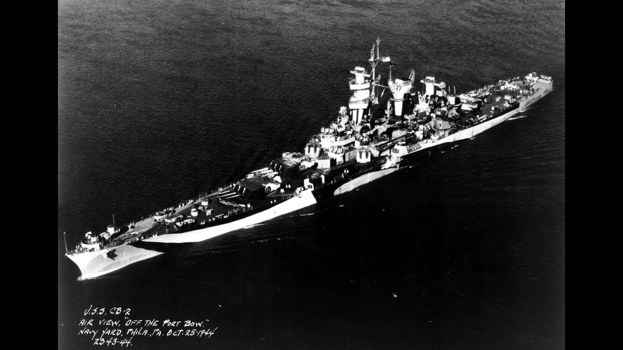
I am trusting that this photo, shown at navsource.org, for CB-2 specifically, is truly the Guam, thus looks similar to Alaska, so I will continue reshaping the "middle" part on the tower, making it angled like in this photo.

Starting here, filing the plastic on the slanted front side. I also filed the sides.
I had no idea, I was about to make a mistake, nearly sanding through the plastic. I later filled the insides with Vallejo putty. I avoided sprue goo, as that would have melted the thin walls I am sure.
I had no idea, I was about to make a mistake, nearly sanding through the plastic. I later filled the insides with Vallejo putty. I avoided sprue goo, as that would have melted the thin walls I am sure.

I have a glass surface I'll use to add a bottom plate to this stand, to try work with something more flat than my table surfaces.

Here I've added Vallejo putty on the insides, because I nearly filed though the plastic.

I am happy with this result. Some putty on the upper left is seen creating a bump, will clean up later.

This shows the job, halfway done sort of, having to wait for the Vallejo putty to harden, before I can finish the left side in the photo. The right side of the middle piece has been filed to match the slant of the upper part. So I had to cut off the deck usually found around where the blue arrow is pointing. I will have to tear the top part from the middle, and sand off 1 mm, then glue on a sheet styrene deck part which I have already cut into shape. The white putty on the inside can be seen through the plastic. Some putty was added to the upper tower part to fix a metal file mishap.

I had to use some masking tape to help keep the flimsy bilge keel part in place, making sure it was angled properly. It was important to use the correct side up/down. This is before I start working with this. The bilge keel should look naturally curved in the end.

I added Evergreen 100 (the smallest strip styrene) around the bilge keel shape, two strips on each side. Will have to fill in the ends and reshape the ends. Maybe go over with tiny amounts of putty and sand flush. Edit: Ah, I nearly forgot, I also intend to add an additional strip, on the very edge of the bilge keel itself, extending its shape out at a 45 deg angle, to match the shape seen in the drawings.

Should look nicer after a around of putty and paint ofc. I must remember to glue on an additional strip at the very edge of the bilge keel itself.

I am very happy with this result. 🙂

With the bilge keels glued on and the lowered stand, the nameplate looked too tall still, so I cut off another 2-3 mm or so. I might round off the corners on the nameplate. The stand has a bottom plate that requires clean up. Edit: I just realized that the text isn't perfectly aligned with the plate, will have to fix that.


I was so sure I had aftermarket USN anchors lying around, but I can't find any. I've even looked in the other ship kit boxes I have. :| So this here, is the kit's anchor.

I had so much fun doing this, the two pieces went on quickly. So, I will add a 0.25 mm tall strip styrene list on top of the sides, which I tried to compensate for when placing the two eh "openings" onto the hull. I also created a slight slant on the insides of the two white parts. Ofc, I had to cut off the moulded openings and sand flush, before I could glue on the two new pieces.

Looking more closely at the symmetry lines for the tower, I had to add some sheet styrene at the front to create a line at the front.

I wonder if the axels are 1) painted red 2) colored brass/bronze 3) colored steel.

This is an unrelated photo, from USS Missouri, but seem to show the two round thingies around the propeller axels found in this kit. So maybe an important part. Also, I would think that the fixtures are sharp to reduce resistance as water pass by. Btw, the four propeller pieces in the kit, look different. One pair has a short base behind the blades, and one pair has a longer base behind the blades, but the drawings show all four having the same shape. Maybe Hobby boss noticed an error halfway through making the four propellers and just didn't bother correcting it for all four. Edit: Uuuh, looks like maybe the two left propellers have a long stem and the right ones have a short stem, weird. I must cut two of them shorter to get a matching quartet.

Next up, figuring out how to best align the four propeller shafts. I think I will glue the four "fixtures" and then keep the styrene shaft loose and glue it on, in the end, after painting the hull. Still unsure if prop shaft is supposed to be colored red, bronze or perhaps steel like I think German ships were.

As expected, my new pointy blade lost its tiny tip making these holes, for guiding a drill bit through the center. I will have to try drill through with a smaller drill bit, and then gently use larger drill bits, and hopefully it will fit a 1,3 mm styrene rod without being too wobbly. Edit: I have since scraped the "holder" part thin, so they have a sharper edge for less resistance with water passing around them.

This works! So, instead of simply trying to drill through from one end to the other, risking getting off center, I instead drilled two partial holes, and then I could use the hole on the other side as a guide for drilling through the whole thing.

I had to use a 1,4 mm drill bit for the 1,3 mm styrene rod. I also used a Tamiya round file to tweak the centering of the holes.

It looks a lot better after thinning the edges (front, right side). It seems perhaps that, all four shafts are at a straight angle, front to back, all parallel, and then, same angle, but angled down a bit vertically, all parallel.


Voila. Done! Fun to finally get to have properly mirrored blades. I will ofc, clean up the details, and try reshape the blades just a little bit to try create a stronger curved shape.

A reviewer claimed that the propellers are too large. Admittedly I haven't checked the size, but I am not really bothered by this potential issue, or at least not now.

The work with scraping the plastic does case some small scratches that has to be fixed later. I am happy with this result. The two inner "sockets" are supposed to be angled a little bit out to the sides, just a little bit. I can't really move the plastic, but I can try re-shape the thing, in some subtle way.

I noticed I had some styrene rods that were hollowed out (cylinder), so I made four thingies to go around the propeller shafts.


So, at this point I had to make sure to drill the two holes, for a "box" structure on deck, before gluing the two deck parts to the big hull. Though, manual show two more holes at the other side of the ship to be drilled, but these holes are not for anything at all (!), so I didn't drill them.

I want to invest in more chisel tools, but I thought I could just try thin this 1mm chisel tool I have, because I rarely use it. I prefer to use the 2 or maybe it was the 3 mm wide one. I will have to keep making this chisel tool thinner to get to carve out the thin slits on this tower structure.

Oh, so after looking at the drawings, I noticed that the upper part of the tower structure, is rounded by a lot towards the top. I had no idea. Seems like a simple job, but I will have to take care to avoid sanding through the plastic when rounding the upper part of the corners.

I noticed at some point, that the ship's hull is really asymmetrical in terms of height, so the bow part is "deeper" under the deck compared to the "depth" below the rear part of the ship. In order to make the deck horizontal while on the stand, I will have to add a thingy at the bottom rear side on the stand, to level the model.

I cut open some holes in the top deck to try reduce the existing tension, but.. I don't think that helps much. Most of my work is done on the forward side, and so I will consider taking the rear part of the top deck off, and try warp the rear section back into shape. The rear top deck was visibly warped when I started, maybe it was the deck part that warped the hull?

I came to the realization that I should use a sharp blade and make a cut all along the edges, and that probably helped a lot. Some plastic snapped in two places on the main hull part, but the deck is ok. Sigh, I will have to spend time figuring out how to straighten the hull shape. I can't stand spending all this time on details, and then the hull shape is freaking warped from bow to stern. :| Well, the difficult part now is over I think. Looking at the now two loose deck parts, there is no warping. I guess the rear top part has a bend to it, but it wasn't warped apparently. Front part also doesn't look warped. I can tell from looking at the sides, that the large hull part certainly looks warped.

I don't want to overthink this, and I just want to keep going. I will add more bits of styrene, to create anchor points, for a stiff rod that I will insert later. I only need to twist the hull by a little bit to get a good correction I think. :|

Done! This took 5 min. I am happy with the result when looking at the model from the side this way. I will have to glue on more bits of styrene to keep the rod in place. I stretched the diagonal, very gently and not by very much.

Looks ok to me, but maybe not 100%. Good enough. 🙂 Note, I have yet to glue on the parts, but at least the hull warping has been fixed. I must be careful to maintain a level deck when gluing on the two deck parts. Btw, the bow shape cutting into the water has to be scraped/sanded a little thinner there at the very front.

Edit: I think 4,5 mm is more appropriate, not 5,0 mm. I am ofc assuming that the illustration used is relevant to this type of weapon, I did not check too closely at that. It does seem obvious from looking at photos, that the discs the barrel is "mounted" to, is too small in diameter in the kit, and also with the aftermarket resin parts.

I got distracted by youtube videos about quantum mechanics. :| For a couple of weeks. Ah, I forgot to mention. I will have to cut new rods for the four shafts, as I do not want to try airbrush these short ones I'll cut longer ones that are easier to hold while airbrushing.

At first I thought "Ah, nevermind!", then I tought I could manage to change the way the rear walls is angled, and so here I am fiddling with even more stuff. One will want a stiff metal files for this work on the outside, as a mushy sanding stick tend to round the edges on larger shapes being sanded.

After heavy procrastination I basically started and finished the shaping of the outside today. Did not take long. Good to get to see some progress again. Result was nearly as nice as I had previously hoped for. Some small amount of putty and a layer of primer will be required to get to properly evaluate the overall result. The inner part will have to be carefully scraped with a sharp blade for thinning the walls, where I added 1mm strip styrene.

This was easy. A 15 min job. Scraping takes a while, but one can also very gently cut along the insides, shaving off plastic little by little, and maybe gently scrape over to smooth the insides. I am very happy with the result. There is always the danger of overdoing the scraping, such that the edge is made too thin, and then the thinnest part sticks out like a sore thumb so to speak.

So this is what my working area looks like. Up to now, I never used it really for modeling, just airbrushing. Soon, very soon, I'll get another 2m wide table on the other end (right side) that I can have stuff on the table, unlike this table which has to be fairly empty, or it will look like a total mess just like it does now. I usually do my work by a large table in the living room, or at some other small table in the living room, and hopefully this will change soon.

The masking tape helps the thin styrene stip in place, and also helps angling the styrene to match the angled side hull. I can probably bend the edge up again later, and clean it up if I want to.

Well, I couldn't really move the tower structure for the catapult ramp, so I filed away plastic to make space for the styrene strip.

I can't get over how fiddly this all is going to be. I will be tampering a lot with the PE railings, then each "leg" for the PE rails will have to match a tiny scratchbuilt base that the PE rails is standing on. Not really room for any errors, I am annoyed already.

There is no hope for me cutting precise parts to glue in, as if being molded parts. Instead, I glue on a styrene part that sort of fits, then I add glue to seal things up a bit, maybe add putty, and then cut and sand things to shape after that. Some more work is required here, I just glued on the basic pieces.

Some more subtle clean-up required. Still, the thin styrene bit isn't fully flush with the hull on the sides. Edit: Looks like maybe a thin edge ought to be added at the very rear as well, so there's an edge all around.

The hydraulic fuel system. Ofc, I found out after I glued it on, it should be lower, so I cut it off again. I have cleaned up the surface and will try again. :|
I believe the fuel for the planes kept at the center of the ship, is stored way aft, hence the fuel line on the outside of the ship. Drawings show the fuel line, going up to the center section, and then into a tower or something, next to the two sea planes.
I believe the fuel for the planes kept at the center of the ship, is stored way aft, hence the fuel line on the outside of the ship. Drawings show the fuel line, going up to the center section, and then into a tower or something, next to the two sea planes.

At the beginning I had to cut off two rings at the bow, sticking up above deck level, so I had to recreate the two rings. Ofc, after scratch building the two, I had a sigh of relief, and started cleaning my table, having forgotten the two pices were still on the green cutting mat. :| Luckily the dumpster diving resulted in retrieval of the one ring I lost. 🙂 Uuh, in second image I had used a 2mm drill bit, then I used a round file to clean it up. I had to use a dust mask goofing around my bin this way and clean up properly afterwards. Venting the room.

Buying this 50W LED work lamp was genius. Nice lighting around the table on the right, and no glare.

I am very happy with this result. Next up, gluing on the hydrauling fuel line on the starboard side, for the second time, and then a good layer of primer on the outside to evaluate the hull. The model is already unwieldy because of the added styrene strips around the deck and down by the two keel thingies.

Good thing I put some primer on, which reveals some of the harder to spot flaws with the plastic/sanding work. I will just sand over, add a little bit of Vallejo putty on the gaps, sand some more, and add more primer.

I am having fun airbrushing the hull and using putty to clean things up making the surface smooth. After adding some primer on the stand, it is obvious some more work is required, at least on the ends which is easily noticeable. I think my new favourite primer paint is Vallejo 74.604 German Dark Yellow (big bottle, 200ml).

Another pass at the stand. Should be a lot better now. After adding another layer of primer, I get to review the result of the putty/sanding work.

More clean up work is required, at this distance the flaws aren't showing in the photo. Nice to know, I should be able to airbrush the red, black stripe and two shades of gray on the hull, and adding a gloss coat, before start working on the railings. 🙂

After mucho puttying and sanding and priming, I think I am done with the basic work here. The main part may need some more black paint, and the nameplate required one or two passes of glossy black, as the nameplate isn't entirely smooth. The layer of glossy black is so thin, it doesn't really fill inn scratches. I will eventually airbrush on gold, and then a gloss coat, then.. airbrush on black, and then.. sand off the black over the letters, hoping the layer of gloss coat will protect the gold. Then.. aibrush on a final layer of gloss coat and then I guess some varnish.

I couldn't make up my mind about the correct colors, so I used a flat brush and put some paint down on paper. I think the deck color ought to be more blue'ish than dark gray, and I ultimately went with 70 drops of Fire Red + 1 drop of black, to avoid having all ships using the same red color at the bottom. Still.. I was not able to fully cover red over German Dark Yellow. I should have airbrushed on dark green as primer I think.

After this, I airbrushed on Alclad II's gloss coat, maybe helping avoiding the paint soaking into the primer, what it seemed like earlier. And I then ended up with patches of lighter and darker red. Will have to sand over gently and try add a final layer of red over this. I also had to add putty on to this at the bow, still a sink mark that had not been fixed.

Finally a paintjob that works out the right way. Perfect mix, no issues what so ever. I will airbrush on another layer of red and then a black line after this, and later after adding the photo etch railings, there is a smaller light gray area at the top side, of the hull that has to be added. Btw, looks like maybe the aft deck is not curved like with the drawings, the model is afaik just flat all the way to the aft, thus I think the light gray paint can't be fully replicated there. It is important to go over each layer of paint with some sanding sponge, to keep the surface as smooth as possible.

I added masking tape at the center but it was pointless. The masking tape wasn't equally wide along the whole length, and I had already a visible demarcation line between the red and the intermediate blue already. :|

No overspray allowed!!! None! 🙂 Instead of using just 'black' for the waterline, I mixed about 60% 'black' and 40% 'nato black'.

Finally. I wanted to get this done quickly so I can now add maybe gently knock down hard edges with a fine sanding sponge and then add a gloss coat to seal the paint. I will probably add oils later, but I've never done that before, so I should be careful. In any case I thought it was a good idea to try be careful up to this point.

Ugh, I had to fiddle with 30 of these, not the bollards but the other ones. Because I had raised the edge of the ship on the sides, I had to elevate the eh 30 thingies here, paired around each set of bollards. I haven't yet glued the stuff onto the deck, as most parts will have to be airbrushed separately, and glued on, after I have finished the railings and all the paint work on the railings and the entire deck.

So there are six more of these. This is the best I can do I think. The other ones are more narrow, this wide one is at the rear of the ship. I will get some thin wire and add some hose line to the roller.

I should add that, for cutting the styrene rod parts, I did not use the tiny saw, I used the nicest Tamiya side cutter to get a clean cut, as close as possible to my pencil mark to get the correct length, with minimum sanding required afterwards, a little risky but at least that part worked as expected. One of the roller sides had to be scratch built, because it was mauled by my side cutter because of stupidity on my part.

Oof. The photo etch railing works seems super complicated. I made this jig instead for now, for the 38 x 50 cal machine gun positions around the ship.

No idea how long this is going to take. Maybe a little each day. I could try first "clean up/fix" all the large railings, and then start working on gluing them on later. The base has to be created with leftover PE parts, another type of precision work I don't quite know how will turn out.
I use a glass plate to cut the PE, to get clean cuts.
I use a glass plate to cut the PE, to get clean cuts.
Opmerkingen
31 12 March 2021, 10:45
First comment, and I'm in.
I'm not sure, but my approach would have been to build up the walls with thin plastic.
Eager to see more
13 March 2021, 05:39
I´m in, too!
The VeryFire detail set provides resin parts for all the gun tubs. Don´t know what would be more easy: thinning down the walls or replacing all this stuff?
14 March 2021, 10:46
I saw the Very Fire upgrade set but, ehe, seems too expensive for me. Instead, I am going with an average improvement of detailing, instead of trying to jam in as much tiny detail as possible. This build should be fairly straight forwards. Waiting for the Master aftermarket stuff, which might take a month perhaps. By the time I get to fiddle with the photo etch I ordered I should have my issue of using gloss coat figured out.
14 March 2021, 11:23
Photo 5. It could be a riased edge. Water can drain through openings... but not shure
20 March 2021, 17:54
I have now looked through what seems to be the easy found photos of this ship class, and, I am thinking, if I could add thin strip styrene all around the hull, it could help hide the base of the photo etch railings, and also add some extra detail that way. 🙂 I will meditate on this.
20 March 2021, 20:32
Btw, this kits comes with several cages on top of the deck, for what has been described as floating nets, but the kit comes with empty cages. Some other modeler had the cages fill with cylinder like objects, presumably some kind of packed netting or something. Seems like an easy "fix" to fill the empty cages with something that maybe looks like what is supposed to lie in the cages.
20 March 2021, 20:34
I have some ideas for the photo etch railings. Not really sure how it might end up looking like. I could add some detailing and raise the railings, which are too low. Ofc, add the outer edge with thinnest styrene strip. And then eh I could look into the possibility of gently scraping the horizontal parts of the railings, to both thin them and make them appear more round. 🙂 Photos seem to maybe show both hard/solid raillings at the bow, and wire, unsure.
6 April 2021, 11:14
Argh, I am still waiting for the stuff I ordered, like metal barrels, and all the medium and AA armament stuff. 🙁
Update: Oh, joy. Tracking data from 20 min ago, show the package arriving to my country, finally. 🙂
6 April 2021, 11:15
Kit overall seems nice. I only found two or possibly four sink marks in total, on the sides of the hull, which can easily be fixed. The added armor on the sides isn't shaped correctly on the top side, it should be slanted, but is flat, not sure if I can fix that or not. The one large hull piece require some very basic sanding to get rid of what I guess are traces of slide molding tech.
I wish there was a good photo of the propeller axels, I have no idea what they looked like in real life.
Update: The non-slanted top side, for the armor plating, can be scraped from being flat, to having an angle, so that problem has been solved, without using putty or anything.
6 April 2021, 11:16
Most ships have a raised edge around the decks. It prevents small but valuable stuff from rolling off the ship. To get water off the deck there are things called scuppers: en.m.wikipedia.org/wiki/Scupper
8 April 2021, 17:24
My plan for the railings, is to first glue on strip styrene to create the outer edge, and then, instead of just gluing on the railings which has a lower edge on it, I want to tediously remove the bottom part of the railings and elevate the railings as seen on photo. This way, the railings have a base in styrene to stand on, and the railings will be elevated to look better. I also want to gently scrape the railings to round the horizontal elements. I think I can do this. 🙂 This way, like seen in photos, the railings are offset from the outer edge, away from the very low hard edge at the very edge coming up from the hull sides.
8 April 2021, 19:15
Btw, I learned just now that there are some official drawings for the CB-2 Guam ship, but has to be requested. No idea what drawings these are, I don't think it is shown, presumably several drawings: catalog.archives.gov/id/53484224
Update: Might be these drawings (5 pages of drawings, but not much):
catalog.archives.gov..;sort=naIdSort%20asc
23 April 2021, 11:36
I just learned from this webpage below showing Guam, also seen on drawings for Alaska, the twin-AA pits near the catapult, apparently are similar to other pits (but has been cut short), and is not as small as kit parts E58 & E57. 🙂 This means I have to create, two more styren AA-pits, luckily I have the guiding shape for that one in particular (also used elsewhere more forward).
navsource.org/archives/04/1202/040202.htm
23 April 2021, 13:04
So.. I am no expert, but it looks like Hobby Boss modelled two of the propellers WRONG.
Instead of mirroring the blades, for two sets of propellers the individual blades were rotated it seems and they sort of look non-functional. It looks like Hobby Boss made two propellers propelling the ship forwards, and two for propelling the ship backwards, and so the arrangement doesn't make any sense. Even if you could rotate individual blade, it would still be wrong as I see it (meaning, can't be fixed, unless making all four props look the same I guess).
I made a facebook post on Hobby Boss' Trumpeters page, but I think they deleted my message, or, I can't see it. I also made the mistake of soliciting for four new props, which ofc in hindsight wouldn't solve my issue, I would only get four same looking props which would be an improvement, but still wrong.
30 April 2021, 15:49
Could you purchase aftermarket props,not ideal but they will be the same.
30 April 2021, 17:48
What do you mean, not ideal but being the same? 🙂
Btw, a photo of the Titanic shows mirrored propellers on the sides, and with a third at the center.
I supposed I could try finish the model, and then leave the propellers off.. and maybe find some aftermarket ones later.
30 April 2021, 20:08
Going strictly from memory here but... The Alaska class suffered from bad mid range speed vibration and if memory serves 2 shafts counter rotated ( 1 per side ) to try to fix the issue with some improvement. So in that case the props would actually be correct.
2 May 2021, 21:15
Ah, no, two of the four Hobby Boss propellers doesn't make any sense, they are really backwards.
I suppose it is possible that there are two counter rotating propellers on each side, instead of pairs on each side. Thanks for the feedback. 🙂
Would be nice if there was a way to confirm the configuration of the propellers. The drawings I have seen doesn't really show how the propellers look except from the side, which doesn't really show anything.
Update: Hm, looking at the side drawing again, I can see that the configuration, seem to be drawn, at least, as a pair of same rotating propellers, on the starboard side.
Update: Weird, the drawings show the rear pair of shafts being parallel, but the forward shafts being angled a little bit out to the sides, surprising.
2 May 2021, 21:39
I either read about it or it was the Drach video I learned that from. The Drach vid is at : Youtube Video
2 May 2021, 21:44
Clair Greenwood, any idea what a "hydraulic gasoline system" is?
According to the drawings, that long shape on the starboard side that I thought was a "skid line", is called "hydraulic gasoline system" on the drawings.
2 May 2021, 21:49
No sir, not off hand, however seems an interesting subject to research. Im sure it must have something to do with replenishment of aviation fuel to/from other ships though. To transfer from one ship to another you would need a pressurized system.
2 May 2021, 22:04
Treehugger, I did a little research on the hydraulic gasoline system. My assumption was close but not 100% correct. It is not for replenishment to or from the ship, but for refueling her own onboard aircraft. The lines are run outside the ship to minimize the chances of fuel vapor, spills inside the ship resulting in a possible explosion in confined spaces.
Here is a link to the original drafts drawn up for the USS Texas explaining operation if you wish to learn more: texashistory.unt.edu..7531/metapth1053385/
3 May 2021, 20:56
Thanks. I don't quite understand what the "pipe guard" shape is doing on the outside of the hull on starboard side, but perhaps the pipe is some kind of fuel dump system for the hydraulic gasoline system? The only text for the shape on the side of the ship are the labels "pipe guard" and "hydraulic gasoline system".
3 May 2021, 22:17
Excellent research and modifications. I will take a seat to follow this interesting WIP.
6 May 2021, 19:36
Oh, bad news. The kit's hull shape is noticeably warped. Well noticeable now.
I had glued on the two deck parts symmetrically so that this wouldn't happen (and I did not force the fit eithe), so I think the single large hull piece was warped from the start. I think the hull design is bad in this regard, unless I was maybe unlucky getting a warped hull. The hull apparently has a twist to it, from bow to stern.
At least when viewed from the sides, the twist is not easily seen.
7 May 2021, 18:12
Gee that stinks, I wouldn't even begin to know how to repair that. Sorry that happened.
7 May 2021, 18:50
I deleted my earlier comment. So, having cut and ripped the two deck parts off the main hull piece, it certainly looks like the hull shape is in fact warped from bow to stern. At least now with the deck pieces off I have some hope of fixing this. :| I still think that the hull shape was warped from the start. Apparently the two deck parts aren't warped as I once thought, but the rear part did have a bend to it, but no warping.
Edit: It seems like, the only way to fix the warping, is to add counter warping. I think I will explore the idea, of inserting a rod of sorts, that warps the hull back the other way, from bow to stern. It would have to be some 1 cm thick wooden stick or something that doesn't easily bend.
8 May 2021, 11:41
Interesting correction, if it works and the wood won't warp it's ok!
10 May 2021, 10:55
Hi Treehugger, regarding the 5 inch guns. I made the same observation and correction with my New Jersey project:
BB-62 USS New Jersey ca. 1984 | Album by stugiii (1:350)
11 May 2021, 07:32
Hm, I guess I should re-check the size. Could be that the discs I have ought to be smaller. I have punching tools for every half mm, so I should be good.
11 May 2021, 09:40
Id did trim of material in the back and bottom of the disk on my build. Diameter is fairly large but the backside has to fit in a 'square' hole
11 May 2021, 11:12
shipmodels.info/mws_..lit=Uss+guam#p937804
Maybe you get some info here too. Nice build so far
11 May 2021, 14:16
Thank you. I am already keeping an eye on that forum thread. 🙂
Next up, I will have to clean up the deck/hull seams, the bow, the bilge keels, and maybe add some propeller stuff, BEFORE I start adding a flimsy edge all around on top of the deck which will be fragile after I glue that stuff on.
Looks like 4,5 mm Ø is a proper dimension for the pivoting disc for the 5 inch guns. I'll work on the 5" guns later.
11 May 2021, 14:32
Ah, I wonder now if maybe the hydraulic gasoline system, shown as a pipeline on the aft starboard side, might be used as a channel, keeping the fuel stored aft and away from the center of the ship, and then they pull gasoline towards the center via the pipe to fuel the planes. I wonder, maybe it works like this.
24 May 2021, 15:21
Excellent, excellent work. Hats off to all ship modelers, the amount of time and effort to produce an accurate replica is staggering. Even a kit OOB will require loads of effort compared to other kit genres. As a retired Sailor who spent all of his adult life onboard warships, a big thumbs up and a hearty "Bravo Zulu"!
3 July 2021, 15:16
Thank you. I have some plans for the railings, which, well, will be a bit tedious, because, I will have to snip off the bottom edge of every railing, and sand every stub clean. This because the railings are supposed to be raised up from the deck, not just glued onto the deck. I think I can do it without damaging the photo etch, but I'lve never done something like this before. Before doing that, I will have to glue on the thinnest styrene strip all along the hull, then add several fixtures that the railings will stand on. This precision work is tedious just worrying about it. 🙂
3 July 2021, 17:26
It seems easier to add a strip on the outside before or after fixing the PE unchanged. This leaves you with the stanchions visible on the inside, but the strip and the railing will be aligned.
4 July 2021, 08:10
Great effort you´re putting in your build! A good inspiration for the day I´ll start my one.
4 July 2021, 08:17
Steven, the kit railings, by the looks of it, are too low. I though at first I could just glue on the railings onto the deck and hide the bottom edge with this outer styrene strip, which would have been ok'ish, but then, the railings is probably too low anyway, so I fix two issues in one go I like to think. 🙂
I will also probably consider, gently scraping every horizontal edge, to round off each edge, which may or may not be a good idea. Presumably, the railings are really hanging wire, but I don't want to pay more money for more realistic looking railings at this point, so I will try use what I have.
4 July 2021, 12:38
Thats an awful nice work area, I could only wish for such accommodations. I, like many, am stuck using the dining room table and told to put it all away... lol
11 July 2021, 23:37
I used to have my computer table and it worked, I just had to clean things up. 🙂 The nice thing imo about my room is all the drawers. All the drawers. 🙂 Ideally, all the stuff could be just stored away in the drawers leaving a clean table, but ofc, that doesn't work, but hey maybe with 10 more drawers I can make it happen. 🙂
12 July 2021, 06:08
Feel free to ask questions. 🙂 Typically, it is fairly easy to make improvements, but one has to make sure you don't end up making mistakes. Having a supply of various styrene products helps, like styrene strips, rods and stuff.
2 August 2021, 19:52
Ooh, I just got an idea. So I problem I have, is finding some kind of material for creating 50'ish stand'offs that raises the photo etch railings up from the added low edge of styrene. I initially though I would just use styrene, but I don't really have styrene that is that tiny. So.. knowing that I will have to remove/cut away the bottom edge of the photo etch railings, I should be able to re-use that left over metal to bend them, and create my 50'ish stand offs. 🙂 I should make a jig of sorts to get same'ish shapes for all the 50'ish stand offs.
8 August 2021, 12:43
I much admire your patience and close eye for the detail. This turns out to become a real masterpiece!
8 August 2021, 19:25
Thank you! 🙂 I have high hopes for this even though the finished model can't possibly be 100% good. I wonder, if I end up making good progress, I might invest in some ship crews as well.
11 August 2021, 13:43
Black Cat offers some really nice 3D printed crew figures. blackcatmodels.eu/en/118-figures
12 August 2021, 00:41
Nice tip. Thank you very much, this is a nice alternative to the Russian one. I like how there is the option to chose between crews with a helmet vs a cap.
12 August 2021, 06:55
I have 2 Black Cat products in a project, they even have running soldiers with guns, though I needed the standing ones.
[img1]
[img2]


12 August 2021, 09:15
Probably a good idea to airbrush them and paint them, on the block, if possible. Much more fiddly painting these tiny figures one by one I learned. 🙂
12 August 2021, 10:53
They're easier to paint if they are glued on a stick. Like that you can also paint the boots.
12 August 2021, 20:06
Ahh right, you can just use superglue to a wooden stick, and then cut off the figure afterwards after painting, like sawing it off just beneath the sole of the boots. I have a lot of small round wooden sticks lying around that I can use for that.
14 August 2021, 08:57
I dunno, I really like how the antifoul red came out in photo 124. It looks quite realistic to me as is. In real life you had variations of color along the hull in all colors of paint.
19 August 2021, 16:55
I thought I would add some oils later on. Hm, now that I think about it, maybe going for totally smooth a paintjob might not be entirely necessary, I never thought about this.
I will airbrush on 'intermediate blue' on the sides, and add the light gray on top of sides later when I get to add the railings. I'll also add the black strip that probably runs right in the middle of what I think might be a torpedo belt armor on the sides. In preparation for the 'intermediate blue' color, I have sanded the whole thing smooth. I managed to create the waterline pretty much spot on I think, so that at least I am very happy with.
19 August 2021, 17:07
Yes a totally smooth paint job, while pleasing to the eye on a model, is not how ships really looked. They were painted by sailors or yardmen with buckets of paint and brushes usually. Im sure you can imagine the different amounts of color in sections being painted by many guys who just wanted to get done. 🙂
19 August 2021, 17:55
Looking closer, after having added the thin bit of strip styrene all along the top edge of the deck there were so many gaps and tiny pits, took a while to go over them. I think I fixed maybe 95% of them.
I am glad I did this extra work, as I learn to just take my time trying to fix things by a little bit of patience.
Uuh, I forgot to mention it, but I will add another layer of red there, and THEN add the black line. I hope I don't forget that order. 🙁
19 August 2021, 20:29
Oof. I think now I must make a plan, a DRAWING , planning out how I can divide the longer photo etch railings, such that the railings best can mist with the existing details. It seems unrealistic to think I can just fiddle with this long PE railing and also mix it into the various details that require modification to the photo etch. :|
4 September 2021, 19:10


