Work in Progress of soldering a little Piper

Of course, this model is again soldered as far as possible, here the fuselage.

Nicely detailed underside

Very nice details, here the firewall; with the engine bonnet, which I sawed off the plastic fuselage. I think the quality of the plastic parts is bad, but we don't need much. I don't know which model they come from.

Already mounted

Rear seat frame and cockpit cover are also soldered in place.

3 (in words: three!) individual struts have to be separated from the plate and installed individually diagonally in the rear. A job for the desperate!

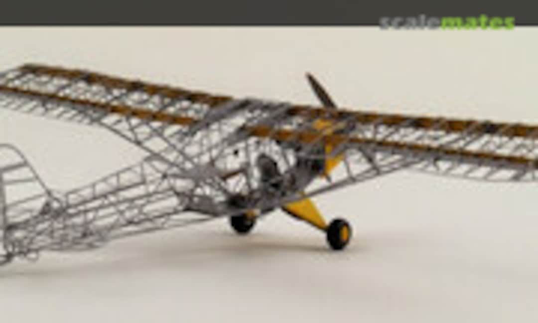
The ribs are bent and two spars are inserted individually into the wings.

A detail picture of the ribs

And in case someone calls out "no solder joints to be seen" again, here they are. All still unfinished, by the way. There are still some small ribs missing on the edge of the nose.

The front spar is continuous, but still gets reinforcements.

Here is a sample of the wing attached to the fuselage, it seems to fit.

This is where self-clamping tweezers are used, ...

... to hold the half-ribs on the front spar. 20 pieces are to be installed, 22 are included on the board.

Here you can see how they push through the covering - oh, there are still two missing far out! But the spar doesn't have a slot! Let's see if I can still get them in.

The tip is supported and held by filigree brackets

Then the wings would be finished - except for the rudder horns on the ailerons, brace holders (which I'm thinking of making completely from brass) and cleaning the whole thing.

After several attempts I finally got the back of the fuselage on! It's so delicate and etched even thinner at the bends that it's hard to handle. Hold it a little with your thumb and index finger - and you've already bent something with your middle finger ...

On the wing I described in the last update that the ribs on the outside were missing. The half ribs (right in the picture) were there, but the slot in the spar was missing. Would have been easier before assembly, but I decided to do some tuning. So I used an etched saw blade to cut a slot in the two outer spars.
Probably equivalent to open-heart surgery - I was warned how easily the wings bend - but it worked.
Probably equivalent to open-heart surgery - I was warned how easily the wings bend - but it worked.

Next mess - the rudder horns. How is the barb supposed to get into the hole in the ailerons? It's brass, not rubber, and Copperfield couldn't get it through either. So I snipped it off and just put the pin in the hole and soldered it.

After cleaning up the soldered joints, the wings are now ready for assembly.

With the Fokker I painted the fuselage and wings separately and glued them together with superglue, but here I decided to solder them together. It is so delicate, otherwise I would have doubts about the "robustness".
So the wedding: I put the surfaces on and soldered them. I measured the edges and worked on the soldering points until everything was reasonably straight.
So the wedding: I put the surfaces on and soldered them. I measured the edges and worked on the soldering points until everything was reasonably straight.

The stability inside should be provided by this frame!

Soldered upside down.

This small frame is placed on the front of the ribs and is supposed to hold the covering (I forgot a picture of the installation).

But in the middle you can see the frame - that is also the current state. The number of etched parts still to be processed has already decreased rapidly. Another window frame is still missing at the top.

Can you build a kit out-of-the-box? Especially if it is a stripdown? You can. But you don't have to. Especially not if you are said to have AMS.
That's why I made the strut from brass. First 0.7mm round brass filed flatter and soldered. It still looks "bulky", but it is more filigree than the flabby plastic struts with 0.9x1.1mm.
That's why I made the strut from brass. First 0.7mm round brass filed flatter and soldered. It still looks "bulky", but it is more filigree than the flabby plastic struts with 0.9x1.1mm.

The length is adjusted, there are recesses in the bars. Of course, they are fixed by soldering.
The smaller supports (about in the middle) are made of 0.5mm brass.
The smaller supports (about in the middle) are made of 0.5mm brass.

Completely from the bottom.

And back to normal.
This has significantly increased the robustness! The whole plane flew off the table onto the floor today due to a little carelessness (stupid carpet monster!) but "only" one edge bow was totally bent.
This has significantly increased the robustness! The whole plane flew off the table onto the floor today due to a little carelessness (stupid carpet monster!) but "only" one edge bow was totally bent.

I didn't like the undercarriage after all, although I actually wanted to use it.

It was made from 0.5 mm round brass and a miniature sheet metal strip. I will add the missing rubber damper covers later.

The Piper-typical side props are ready.

This most filigree window still belongs on the wings and the back of the fuselage, it is drawn the wrong way round in the instructions!

After soldering the rudder, an etched part strip is added to the fuselage spine and tail unit attachment.

One of the most delicate parts of the kit: the tailwheel holder with linkage chains.

But it looks different from the drawing!

Nevertheless, soldered on, the innards of a clock can't be more complicated!

And looks great, I think.

This is getting pretty darn close to a Piper and is now ready for a spirit wash to remove the colophony.

The control sticks (double control) also had to be mounted, according to Eduard the plastic things. There were two 0.7mm holes in the base plate. How should I fix this bead? It looks like nothing!
One of the easiest exercises: scratch in brass. 0.5mm brass with 0.7mm tube piece as handle and base plus narrow 0.9mm ring as stop.
Top plastic, middle parts, bottom finished. Yes!
One of the easiest exercises: scratch in brass. 0.5mm brass with 0.7mm tube piece as handle and base plus narrow 0.9mm ring as stop.
Top plastic, middle parts, bottom finished. Yes!

I wasn't finished with the soldering after all, when I was looking through the small plates I discovered the handles. According to the construction plan, I had left them out so that the fuselage could be laid down better. So I soldered them on.

Fiddle in and solder the control sticks.

In addition to the handles, the boarding aid also had to be added.

After thorough rinsing with alcohol to remove the colophony (luckily I have an air exhaust system!) I brushed the brass with Mr. Metal Primer (it's clear, so no picture) and later the Piper in grey. It takes time to get all the corners inside.

Eduard indicated a wood tone for the entire wings, but this is wrong, because the ribs were made of aluminium (there is a great video). In any case, the spars were made of wood, so I painted them.

Another view.


For the completion of the interior some parts are still needed, e.g. the instrument panel.
A nice etched part, already matted.
A nice etched part, already matted.

Despite the tiny scale, the instruments can almost be read on the enclosed film after I whitened the background. Unfortunately I forgot to take a picture after gluing (with white glue), unfortunately you can't see much of it at the end.

The rear seat with straps. It has no classic backrest, the pilot can throw himself into the harness.

The etched frame of the front seat ...

... and in the complete view.

The fuel tank was soldered ...

... and painted with Alclad Alu.

There was also work to be done on the wheels. The brake discs are included as etched parts (top), but the outside shows terrible sink marks (bottom wheel) - but there are no etched parts for that.

During a conversation with my friend Claus I had the idea - you have a lathe. So today I turned the special punch-and-die and punched the lids out of 0.05mm brass. Actually, there should be a raised "CUB" on it, but even the smallest letters are still too big.

The tyres got the tyre colour from Gunze, the discs Alclad Steel.

The tail wheel should be carved out of the plastic part, but this is too thick for the etched parts of the holder. So I scratched it out of a black casting and added a 0.3mm brass axle

... and mounted after painting with the tire paint.

I airbrushed the outer covers yellow after priming. As you can also see, the cockpit was completed.

Tank and instrument panel are also mounted.

It took 21 attempts and a far greater number of curses to fit the front seat, as it was almost impossible to thread it through the remaining openings.
The ribbing of the tank can be seen nicely under the instruments, just like on the original. And here you can also see the rudder pedals - 4 etched "T", the smallest etched parts of the kit! Took a lot of time, as the 4 flicked out of the tweezers during assembly and it took me half an hour to wrest it back from the carpet monster!
The ribbing of the tank can be seen nicely under the instruments, just like on the original. And here you can also see the rudder pedals - 4 etched "T", the smallest etched parts of the kit! Took a lot of time, as the 4 flicked out of the tweezers during assembly and it took me half an hour to wrest it back from the carpet monster!

I painted the thicker handles of the control sticks (see further ahead) black, the black throttle sliders on the left cockpit wall got yellow handles.

These yellow wheel supports must first harden before they can be glued.

Rigging. Some will ask themselves, bracing? Surely this is not a WWI biplane and it is already braced?
In the skeleton drawing linked earlier, the surfaces are braced crosswise on the inside and I was of the opinion that I absolutely had to reproduce this.
In the drawing, there are such strange parts painted in, it almost looks like the ribs - but in a different grid. The video gives the resolution - these are tubes so that the bracing doesn't squeeze the ribs together.
So I soldered brass 0.5 to 0.05mm remnants.

Filed into shape and slightly bent to accommodate rigging

Painted dark grey ...

... and glued in the 8 supports of version 1.0 (that sounds bad!) according to the plan.

Then I tried to glue in "invisible yarn" with superglue. But that came to nothing! Even after what felt like 100,000 attempts, it looked terrible. Superglue didn't hold, when I tried to tighten a corner with heat, another spot opened up again, etc. .... Having to build THE plane completely with superglue would be the ultimate horror for me!

And skewed bracing does not look good.
Conclusion: Abort. Give up? No way!
0.5mm brass wire, 0.7 and 0.4mm tube and 0.05mm sheet metal ...
Conclusion: Abort. Give up? No way!
0.5mm brass wire, 0.7 and 0.4mm tube and 0.05mm sheet metal ...

... give the supports version 2.0, after I had looked at the part in the video again. The support plate was also round. The invisible sewing thread can now be threaded through the 0.4mm tube.

All 8 supports are finished, here still a bit filed into shape and washed with alcohol.

After priming with Mr. Metal Primer, they are painted dark grey. The version is also closer to the original in the video.

Second try to rig it is started.

Hard to photograph, but both sides are tightened and glued! Partly I had to unthread again because I noticed that I went through the wrong opening of the ribs and the tension wire kinked at one rib.

Another detail macro ...

... and in comparison to the drawing (against the light background the crossing out is better visible)

Since I couldn't find a better engine in the aftermarket, I had to do it myself.
So I filed an M3 screw into shape.
So I filed an M3 screw into shape.

A hammer, an old cutting mat, barbecue aluminium and a few blows on the screw head result in this after a few attempts (and adjustments with a file). If one flank is too steep and you hit too hard, the aluminium cracks.

And the best specimens were carefully removed from their aluminium environment with a cutter - the Piper now has four metal covers for the cylinder heads.

With the covers, metal housing and black cylinders, the Continental Boxer already looks pretty good to me, considering the size.
The motor housing was not glued to the propeller shaft as intended (would have been drilled crooked), but only pieces of it were inserted and the motor glued so that everything sits straight. Extended with a piece of cast iron branch and then drilled 0.7mm for the brass shaft.
The motor housing was not glued to the propeller shaft as intended (would have been drilled crooked), but only pieces of it were inserted and the motor glued so that everything sits straight. Extended with a piece of cast iron branch and then drilled 0.7mm for the brass shaft.

Even though you won't see much of it, I have added the valve levers below.

At least the typical boxer cylinder offset is well reproduced.
I have added ignition cables with blue enamelled copper wire.
I have added ignition cables with blue enamelled copper wire.

The Piper-typical air deflectors, as Eduard has provided them ...

... now also fit much better to the large cylinder heads, the ones from the kit were much too small.

For a defined reference point for mounting the motor, I have inserted an additional wall.

The exhaust holes are also drilled.

Have I forgotten anything else or can I glue the cowling?

The undercarriage was not quite finished yet.
I had newly constructed these chassis struts in brass, but note the thickening. In the original, there are the tightened rubber dampers, which are covered to protect them from petrol, oil and sun.
I had newly constructed these chassis struts in brass, but note the thickening. In the original, there are the tightened rubber dampers, which are covered to protect them from petrol, oil and sun.

How to reproduce it, and how to do it better than this rounding?
First a thickening with the all-purpose weapon Tamiya tape.
First a thickening with the all-purpose weapon Tamiya tape.

And then my friend Claus had the brilliant idea of using aluminium foil (matt side outside) - you can still fold and crumple it nicely, because there are press studs or rivets on the original. That worked out great.

This was then, of course, painted black.

The airbrushed yellow undercarriage supports from the kit are also mounted. These are the only covered parts, so to speak, and could have been replaced by 2 brass rods each. But this gives a nice touch of colour.

Now I have to work again with 0.7mm brass, because new exhaust pipes are needed. After the bend, the plastic parts were too short for me to disappear under the cowling and were not boxer-typical, i.e. on one side to the wrong side of the cylinders.

There is not much left of it.

In the Kopro kit there were two knobs that were supposed to be the outlets of the silencer. But my drawings and photos all show only one outlet, and it should also be a tube.
So 0.7mm tube with a piece of 0.9mm for thickening (already soldered on the back) plus another one that I first turned thinner.
So 0.7mm tube with a piece of 0.9mm for thickening (already soldered on the back) plus another one that I first turned thinner.

The thick pipe, painted with Alclad Alu, represents the thermal insulation around the exhaust, the inner pipe is painted with Alclad Exhaust Manifold, i.e. exhaust colour.

From below you can see the distance between the pipes quite well.

The other exhaust pipes are of course also in exhaust colour.

The whole thing again from below, already with the oil cooler. One could also have glued it cleanly.

On its front is another etched part from the kit.

I originally wanted to convert the air deflectors so that they were closed at the back. But then I wouldn't have been able to fit them, because I wouldn't have been allowed to fit the cylinder head covers beforehand! Even if the AMS-infected community will not like to hear this - you can and must leave the church in the village and mount an etched part as intended.

The much too thick propeller shaft was replaced by brass, a screw plate is included in the kit by Eduard. But what is that 1mm knob at the front of the propeller? Searched for photos in the net - ah, that is a tube with holes, probably for starting. So it has also been remodelled.

The protective edge of the propeller was metallised, and with courage I glued the finished cowling in front of the Piper.

And a few more impressions.


Done!
Comentários
34 18 May 2023, 16:22
Now I'm done with adding all the pics from the old build log and translating the picture description. I hope there are not to much errors.
18 May 2023, 18:49
Wow wow wow Bughunter. I'll take my hat off for you. I've already seen your other album covering this build but with the captions it gives so more info in how hard it must have been to achieve this result. The eye for detail is very "Bughunterlike" 🙂. I really like the work on the braces supports and the engine, great scratch building! Amazing build overall!!
23 May 2023, 19:44
Very nice superdetailing of this Stripdown-kit. May I ask how you prep those delicate parts before soldering? Light sanding and an alcohol wash? How do you avoid solder points to be disconnected again when soldering in the vicinity? Do you tin the parts before and apply only heat when they are aligned or you proceed differently? Which tin and which temperature do you use? Sorry for all the questions but your results are convincing and those points are the ones I still struggle with when soldering delicate parts.
24 May 2023, 01:49
Thank you very much mates!
Temperature? I don't know, as I used a small 20W soldering iron without temperature control from DIY store. But it has a real copper tip which is important for me. If the tip is to thick to solder inside I replaced it by a thick copper wire.
I do not prepare the brass parts. The neighbor soldering points can be protected with clamping tweezers and only do it quickly.
I use colophony as a flux. Yes, the one from the violin store. It's soluble in alcohol and so you can make your own solder lacquer.
The main thing are nearly 50 years soldering experience 😉 I was drilled in this as a young guy while training to be a telecommunications technician.
24 May 2023, 09:04
Thanks Frank for the details. Yeah, experience definitely matters, as I experience the hard way. But improving is part of the fun. 🙂
24 May 2023, 12:20
My anxiety went through the roof just looking at this… magnificent work indeed 👍
25 May 2023, 13:40
I am very pleased that you like the soldering! The finished model was to be seen here for a long time, but there you can hardly guess what is under the paint.
25 May 2023, 20:28
Album info
According to the pictures this was done between 19. Okt. 2014 – 2. Jan. 2015, loooong ago.
I added all pics from the build log and translated it from German.